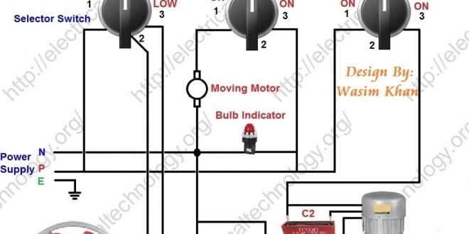
Air Cooler Wiring Connection Diagram
+-+Copy.jpg)
Vt Commodore Ignition Wiring Diagram, Complete Wiring Diagrams For Holden Commodore VT, VX, VY, VZ, VE, VF, 5.36 MB, 03:54, 32,796, John Amahle, 2018-08-01T19:37:41.000000Z, 19, Vt Commodore Ignition Wiring Diagram, to-ja-to-ty-to-my-to-nasz-swiat.blogspot.com, 1272 x 1800, jpeg, bcm pcm 12j swiat nasz, 20, vt-commodore-ignition-wiring-diagram, Anime Arts
When autocomplete results are available use up and down arrows to review and enter to select. Touch device users, explore by touch or with. Basic evaporator switch wiring schematic. Room air cooler wiring diagram # 1.
Air cooler wiring connection diagram at times the wires will cross. Room air cooler wiring diagram # 2 (with capacitor marking and installation) note: A compressor, condenser fan motor and evaporator fan motor. Evaporative cooler motor wiring diagram. To properly read a electrical wiring diagram, one offers to learn how the particular components in the system operate. For instance , if a module is usually powered up and it sends out a new signal of half the voltage and the technician will not know this, he would think he has a challenge, as he would. Room air cooler wiring diagram # 2 (with capacitor marking and installation) room air cooler wiring diagram # 1. The load will slow the motor down. 3 speed cooler motor wiring as we have shown in the diagram, we will attach a main supply wire from the back to the p point of the rotary switch, and place the black wire of the cooler on the number 1 part.
Room Air Cooler Wiring Diagram # 2. (With Capacitor marking and Installation) | Electrical
+-+Copy.jpg)
wiring.cdr by Usman Ahmad - Wiring Diagram for Mini Air Cooler pdf - PDF Archive

Room Air Cooler Wiring Diagram # 1 | Room air cooler, Cooler connection, Diagram

Air Room Water Cooler Wiring Diagram - Electricalonline4u

Cooler Connection Diagram || 4 wire cooler motor connection diagram || Air Cooler Wiring - YouTube

Air cooler wiring - YouTube

Room Air Cooler Wiring Diagram # 2. (With Capacitor marking and Installation) - ELECTRICAL

Evaporative Cooler Wiring Diagram

Get Residential Air Conditioner Wiring Diagram Download

Mastercool Evaporative Cooler Wiring Diagram - HUDAOFFICIALBLOG

