B16 Vtec Solenoid Wiring Diagram

Vt Commodore Ignition Wiring Diagram, Complete Wiring Diagrams For Holden Commodore VT, VX, VY, VZ, VE, VF, 5.36 MB, 03:54, 32,796, John Amahle, 2018-08-01T19:37:41.000000Z, 19, Vt Commodore Ignition Wiring Diagram, to-ja-to-ty-to-my-to-nasz-swiat.blogspot.com, 1272 x 1800, jpeg, bcm pcm 12j swiat nasz, 20, vt-commodore-ignition-wiring-diagram, Anime Arts
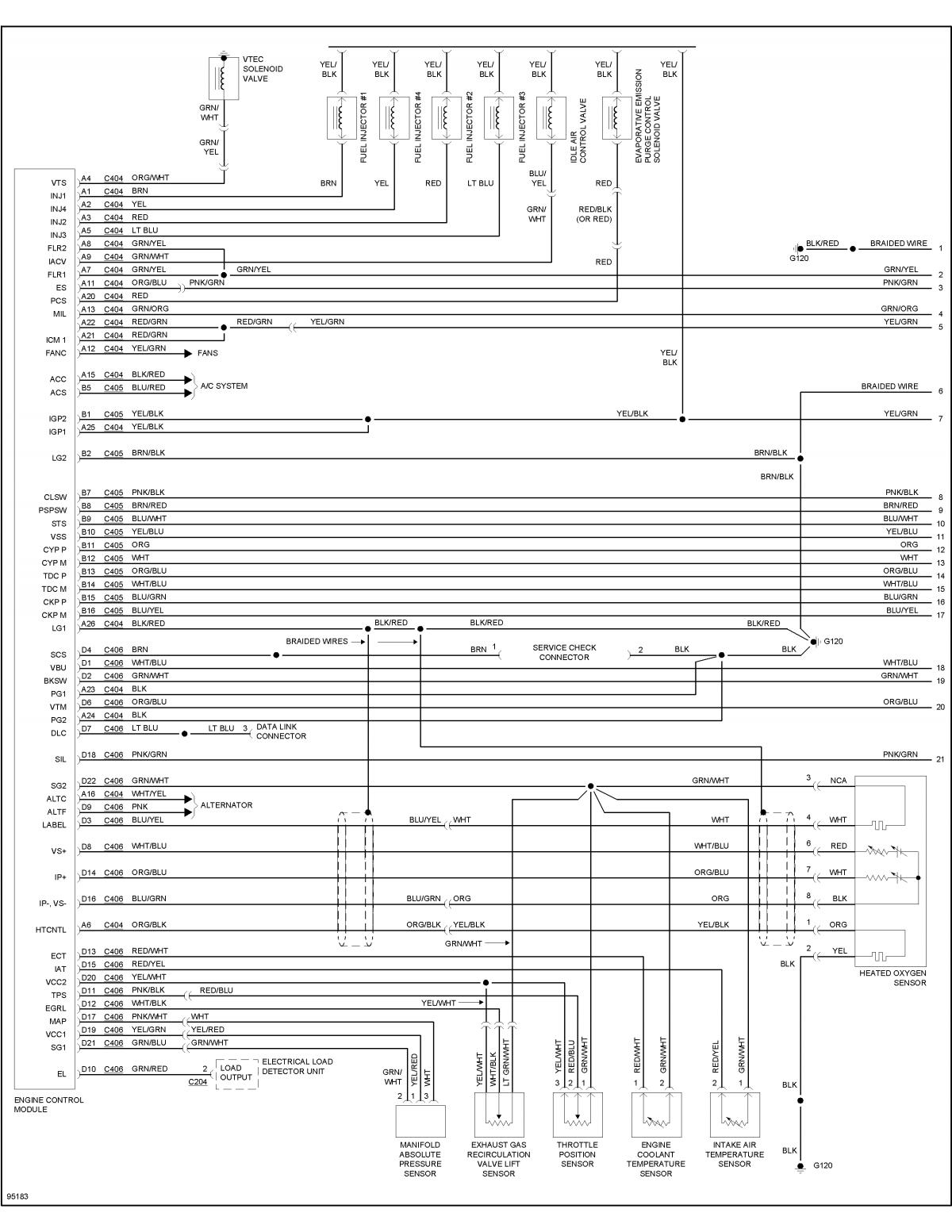
I think it is dpfi. Adding vtec to an b20v/lsv conversion p28 ecu chipped for dohcusdm solenoid : Vtec solenoid goes to a4, vtec switch goes to d6 and ground jdm solenoid: The wire at the ecu (pin a4) starts out as an orange/white wire.
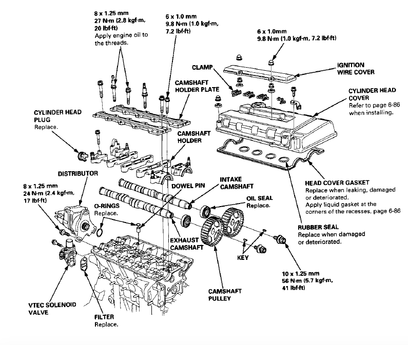
It finnally turns into a green/white wire, which is what color the wire on the connector should be. The wire at the ecu (pin d6) starts out as an orange/blue wire. It then turns into a blue/black wire, which is what color the wire on. Additionally, you can also run the wires from your shock tower to the solenoid and vtec spool filter to save yourself money and time. If your honda civic cx is not using a heated 02 sensor (four wire oxygen sensor) you will need to. B16 and b18 vtec engine diagrams facebook; B16 and b18 vtec engine diagrams. By auch, june 11, 2006 in tech help. Probably just an exploded diagram of engine components (ie.
HOW TO: rebuild and install H22 LMA's in B16 ***PICS*** - Honda-Tech - Honda Forum Discussion

Civic b16 Wiring in custom chassis - Honda-Tech
I have a 92 civic, and am transplanting my b16 a1 v-tech with turbo and chrome-pro tuned ecu

I have a b16a jdm motor and my vtech will not kick off i hooked a switch up to the solenoid and
Schaltplan Motorschutzrelais

Civic b16 Wiring in custom chassis - Honda-Tech - Honda Forum Discussion

EM1 - Harness Question - B16a2 => B18c - Honda-Tech - Honda Forum Discussion
Honda B16a Wiring Diagram Engine - Wiring23

B16a Obd0 Wiring Diagram - Wiring Diagram

