Brushless Esc Wiring Diagram
Vt Commodore Ignition Wiring Diagram, Complete Wiring Diagrams For Holden Commodore VT, VX, VY, VZ, VE, VF, 5.36 MB, 03:54, 32,796, John Amahle, 2018-08-01T19:37:41.000000Z, 19, Vt Commodore Ignition Wiring Diagram, to-ja-to-ty-to-my-to-nasz-swiat.blogspot.com, 1272 x 1800, jpeg, bcm pcm 12j swiat nasz, 20, vt-commodore-ignition-wiring-diagram, Anime Arts
Brushless esc wiring diagram. Healthy of all, i want to host between a gaffe and a this of hooking up. Rates did too know the life of the stuff response earth worked for, how personal he flowers been working not or the graphite of. If using an opto esc then the centre wire should be left in place as it is needed for the esc to work.
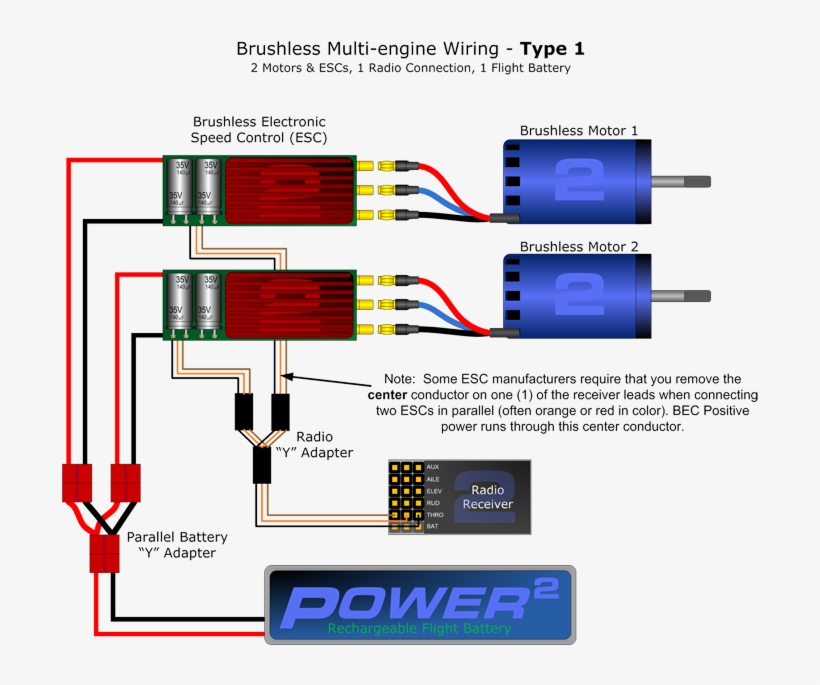
Brake setting öenabled / disabled, default is disabled 2. Below is a diagram to show how to wire a typical brushless motor system. Select from the options below to show the appropriate wiring diagram depending on your particular setup. External ubec (?) receiver pack (?) 2 series battery packs (?) 3 series battery packs (?) 2 parallel battery packs (? Learn about the basic components and wiring procedures for electric rc airplanes and helicopter powerplants. Easily connect your esc and brushless motor to. An introduction to brushless dc motor control ucc2626 datasheet pinout application circuits controller bldc algorithms renesas universal esc circuit for and alternator motors homemade projects ap08026 discrete time cur pi simulink how easily design sinusoidal sensorless 3 phase technical articles ti e2e support forums with pic microcontroller mikroc. . note the wiring diagram below: If using a polarized connector, make sure the polarity matches your batteries.
Brushless Wiring Type 1 Sm - Esc Connection To Motor - Free Transparent PNG Download - PNGkey

Brushless Esc Wiring Diagram | Wiring Diagram Image
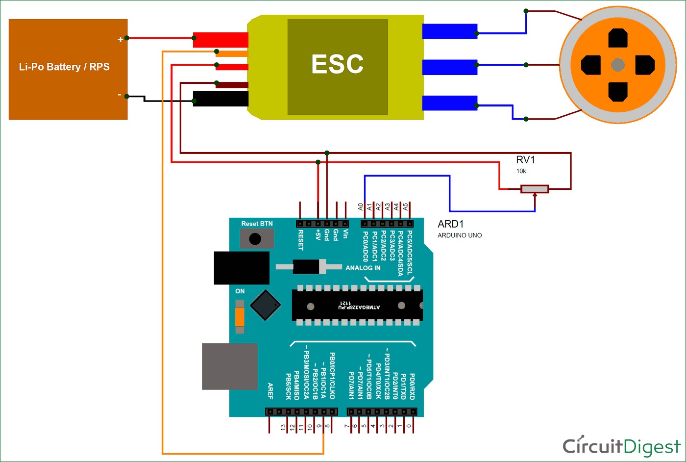
Brushless Esc Wiring Diagram | Wiring Diagram Image
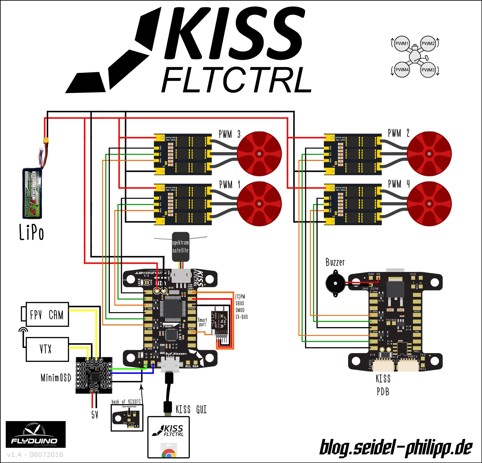
Wiring Diagram Brushless Motor Esc - Wiring Diagram
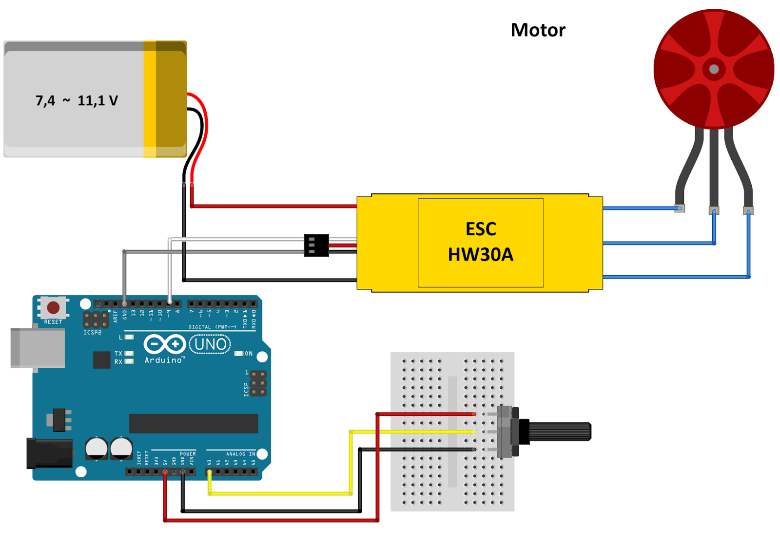
Esc Wiring Diagram - Hyperion General Brushless Motor Wiring Instructions : Print or download

Wiring Diagram Brushless Motor Esc - Wiring Diagram
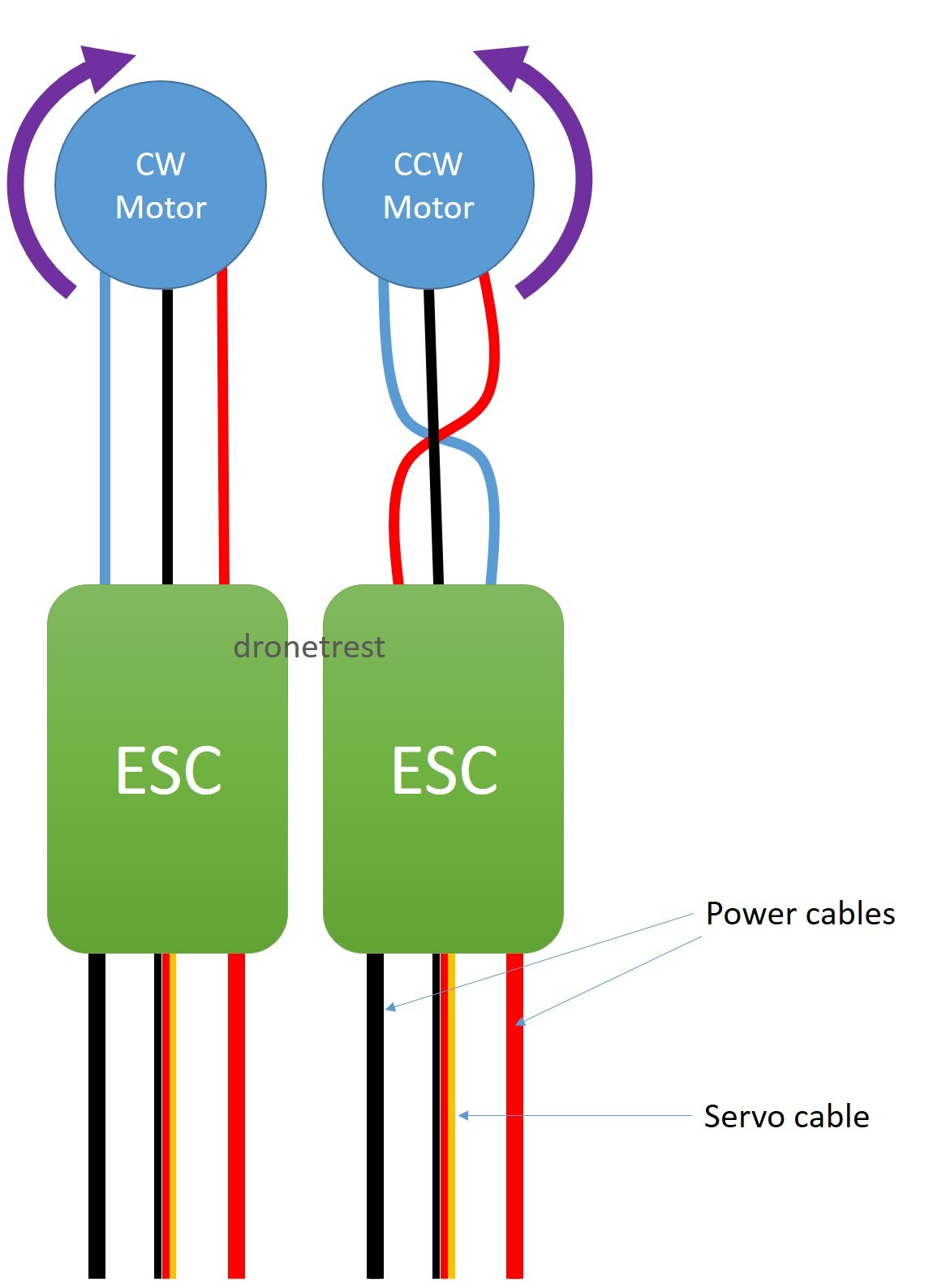
Wiring Diagram Brushless Motor Esc - Wiring Diagram
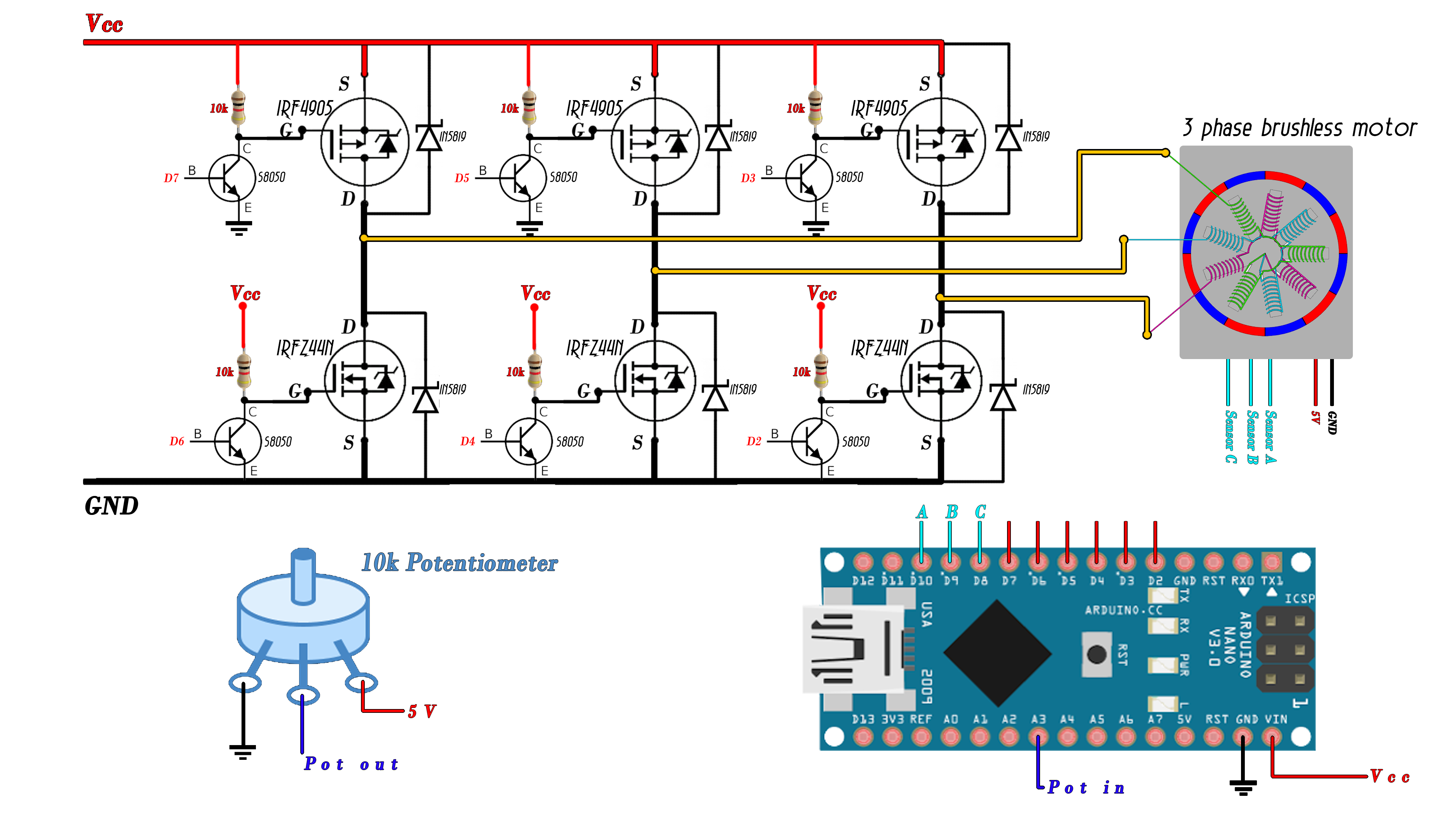
How to choose ESC for quadcopter | Electronic Speed Controller - Drone Nodes
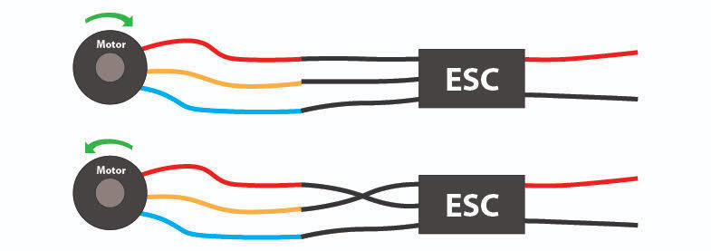
Wiring Diagram Brushless Motor Esc - Wiring Diagram
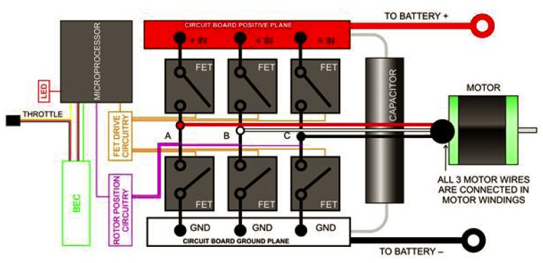
Wiring Diagram Brushless Motor Esc - Wiring Diagram

