Camstat Fan Limit Control Wiring Diagram
Vt Commodore Ignition Wiring Diagram, Complete Wiring Diagrams For Holden Commodore VT, VX, VY, VZ, VE, VF, 5.36 MB, 03:54, 32,796, John Amahle, 2018-08-01T19:37:41.000000Z, 19, Vt Commodore Ignition Wiring Diagram, to-ja-to-ty-to-my-to-nasz-swiat.blogspot.com, 1272 x 1800, jpeg, bcm pcm 12j swiat nasz, 20, vt-commodore-ignition-wiring-diagram, Anime Arts
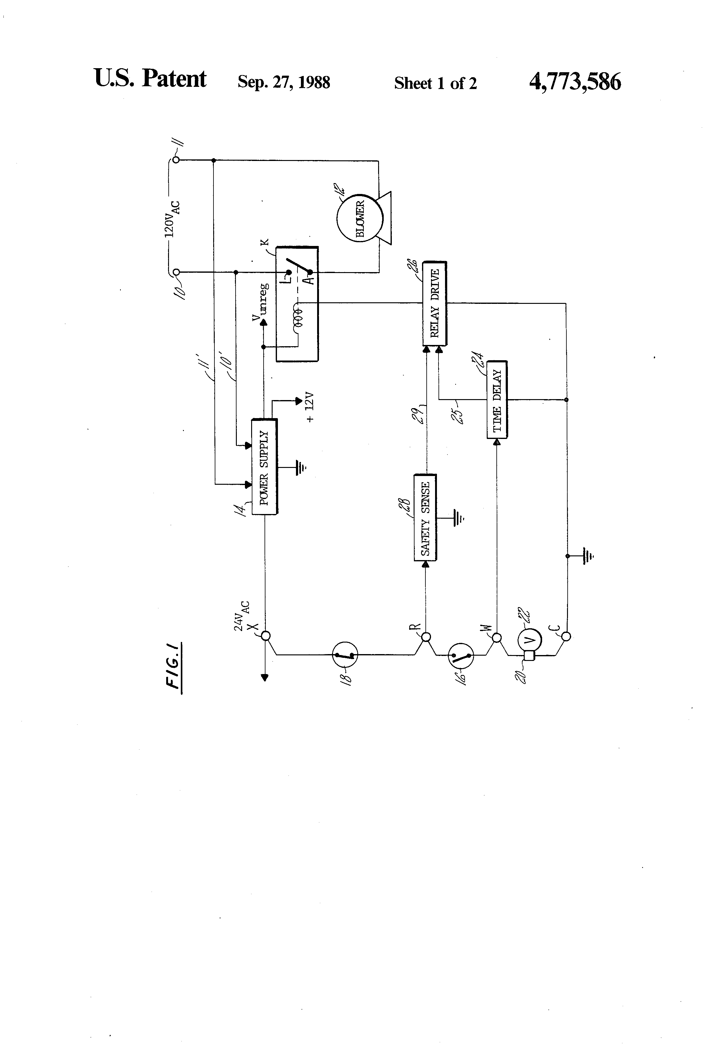
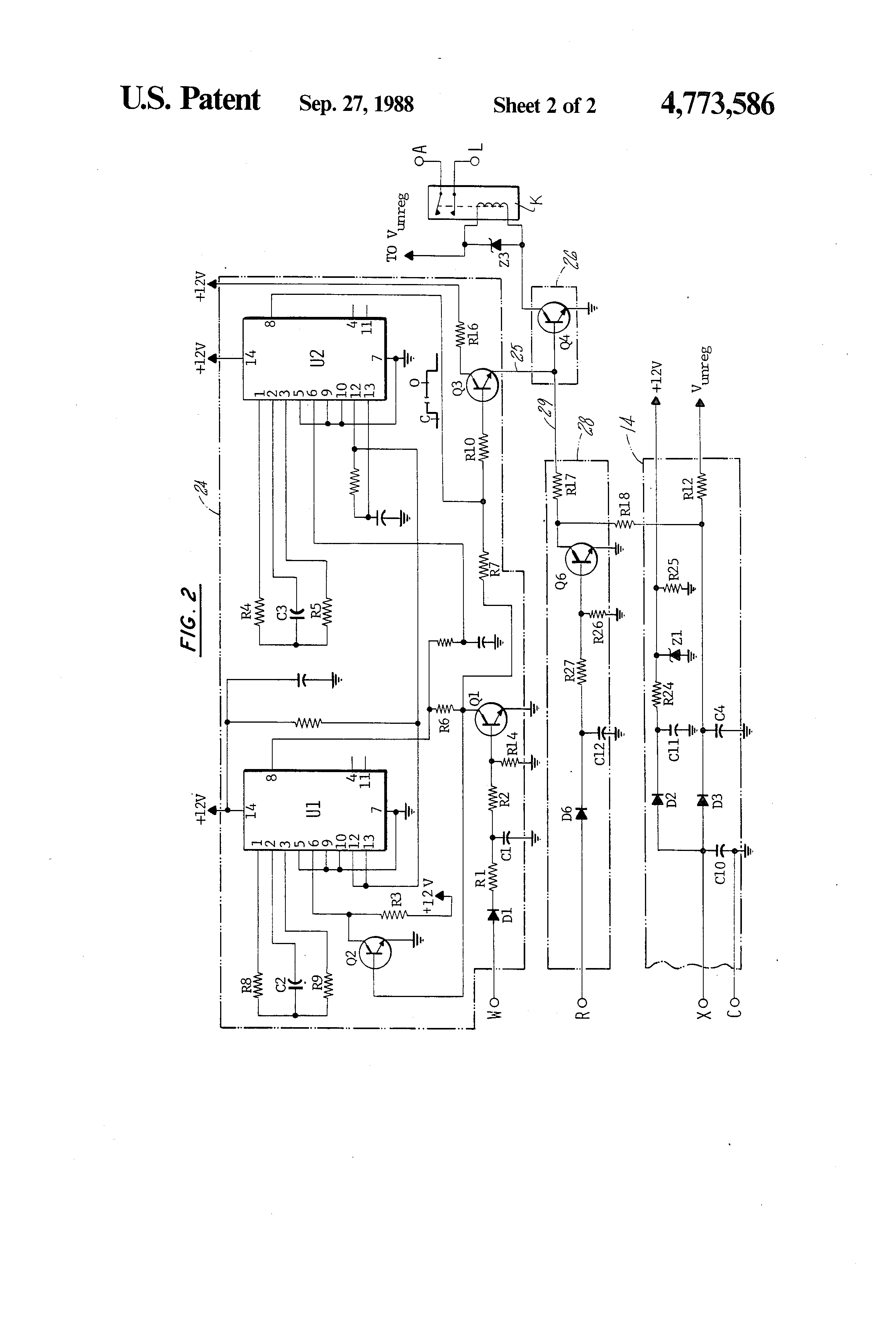
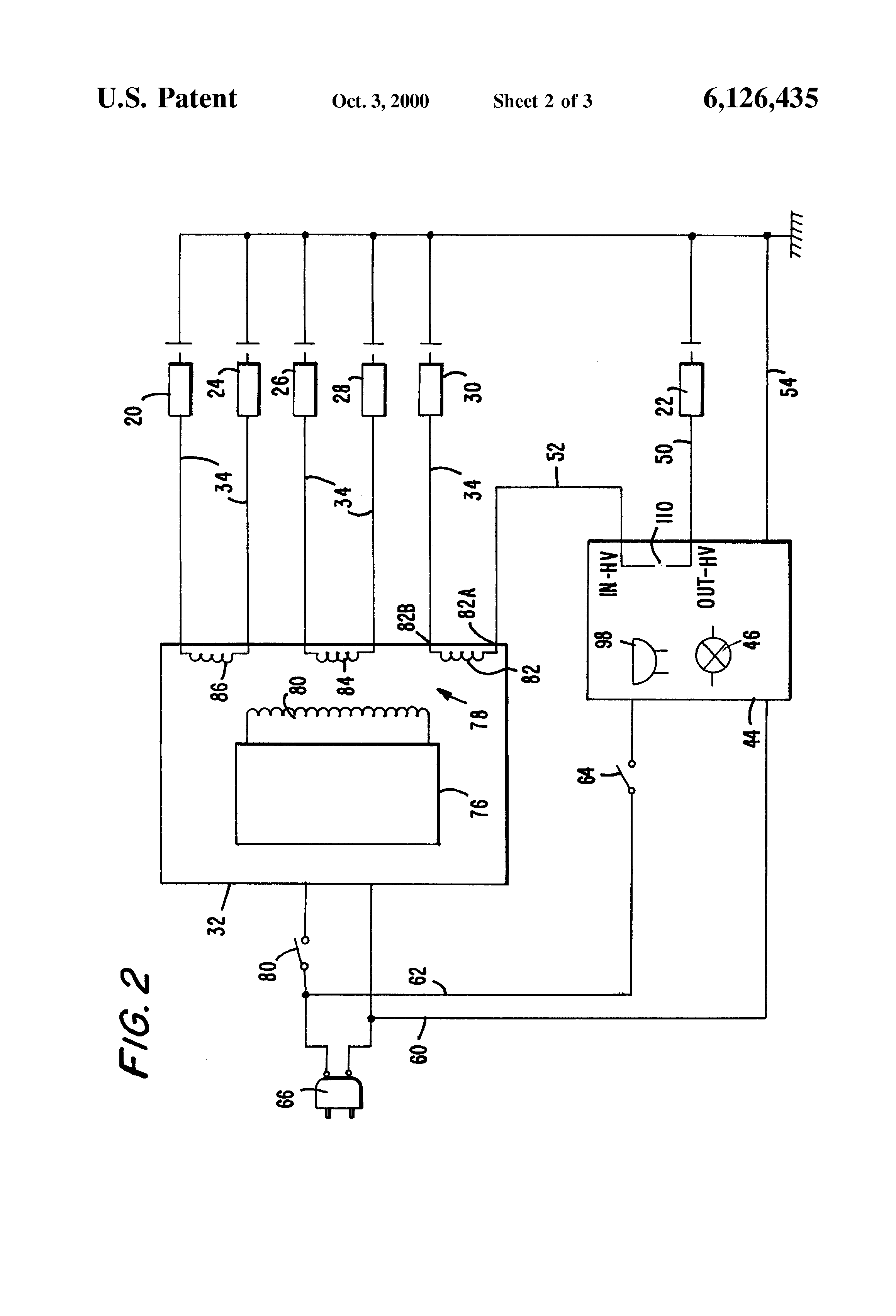
Terminals 5 and 6 on the camstat as shown on the wiring diagram i provided you are for the low voltage/limit wires. 2 and 4 are for the fan switch on the camstat. The honeywell fan side which is left on the diagram i provided you will use 2 and 4 wires of the cam stat and the limit which is right side of the honeywell will be used for the 5 and. This blower control relay and limit.
Time start fan control for heat assist. Turns off blower as a function of temperature at dial setting for fan. Adjustable furnace temperature limit to match existing setting. 25 to so limit t. Limit fa47ts series fan controls witime start fan control (replaces all fa47ts series controls) these are special fan controls with a built in 'heat assist' time delay. One method uses a set time, controlled by the furnace's main circuit board, to turn on the fan. The original method for automatic fan operation in a furnace is by using a temperature measuring device to activate the fan when a specified temperature is reached. Supco offers the complete line of camstat controls. L59 series limit controls • spdt switch • user adjustable temperature setting fan part a1 part length temp off fixed no.
Camstat Wiring Diagram

Camstat Wiring Diagram
Camstat Wiring Diagram
Falts57c-05t-120-a Wiring Diagram
Camstat Wiring Diagram

How to Install & Wire the Fan & Limit Controls on Furnaces Honeywell L4064B & All White Rodgers
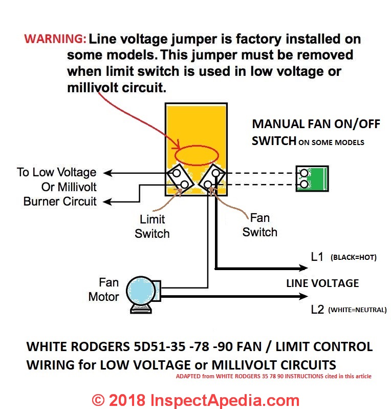
How to Install & Wire the Fan & Limit Controls on Furnaces Honeywell L4064B & All White Rodgers
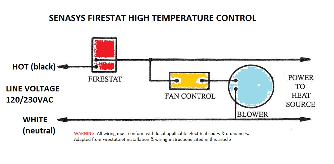
How to Install & Wire the Fan & Limit Controls on Furnaces Honeywell L4064B & All White Rodgers
Honeywell Fan Limit Switch Wiring Diagram | Fuse Box And Wiring Diagram

honeywell-fan-limit-switch-control | High Performance HVAC Heating & Cooling Reviews

